
PROGRESS LOG
updates of the project showing progress

Progress 9/15/26-9/21/26

Michael:
Spent the week working on the final CADD designs for the housing of the arm. Each part will take 22 hours to print so i sent just the base for now to print in order to see if I need to rework anything. The print stopped around 80% complete due to a clog but enough printed in order for me to test to see if the components we bought will fit. The person whose printing the design for me is bringing it on Tuesday 9/22/26. Once i know everything fits ill print the arm components. Below is my designs showcasing how everything is going to fit up and what the real world 3d print look like.
The CADD drawing below shows placement of the locking pin that will help hold modules in place when there is a loss of power. You can also see where the electromagnet will sit. The pogo pin are recessed so only the front part is flushed with the surface of the base unit. This is the base unit of the project.

This CADD drawings shows an overall view of the entire arm. For now I used 3 Ardunios stacked in order to get spacing right and simulate the final PCB. Once i know the base is good, I will print the forearm this week


Troy:
This week I finished making the human machine interface enclosure and mounted all of the internal and external devices. Discovered I miscalculated the number of terminal blocks I would need so I ordered more of those alongside more 16 AWG MTW. Furthermore, I attached din rail clips to the back of the Raspberry Pi CM5 and clipped that in place. Placed some temporary wiring to test power the system and make sure all components work, and they did. Cleaner wiring will be made permanent once the terminal blocks arrive. Continued working in KiCad and got all the footprints and schematics for every component uploaded into a custom library. It is just now a matter of connecting the components together and organizing the layers before sending off to print.


Progress 9/22/26-9/28/26
Michael:
Received 3D printed housing and found several errors with the print. Main errors were just sizing of holes for components. I met with my boss to ask advice on 3D-printing as he had created an entire 3D printing lab at work. He suggested several changes within my design as well as recommendations for prototyping. The main change was the way the pieces fit together. Since the main issue mechanically is with the joints connecting, we were able to come up with a more candy shape housing that adds extra stability of the design while keeping the original concept. This candy shape design will allows for the the arm to stay together without use of screws.
I ran out of time over the week to finish it but plan on finalizing everything by end of the week and get it printed. meanwhile the new design is showcase below. My other goals for this week is to start buying the main frame to mount everything to.
Because of the redesign effort I did not have time to change anything on the website. I will work on that over the next few weeks. I wanted to get the redesign finished so we can start final assembly and testing in October.


Troy:
This week I worked on the internal wiring of the control cabinet, still waiting on some more terminal blocks to arrive. Also made significant progress in KiCad for custom printed circuit board. Electrical schematic is finished, just need to adjust physical connectors and component placement. Ran into unforeseen issues with some symbols and footprints not being available, so I made them by hand which took some extra time. Sending out the PCB for printing by Friday.

Progress 9/29/26-10/6/26
Michael:
I spent a lot of time updating the website this week. I plan on going to the store to buy the remaining base structure for our build. No update photos on the 3d prints because my printer guy was out of tow for the weekend. I finished small details on Thursday night and he wont be back till Monday the 5th. When he gets back on the 5th he's going to start printing and i should have the parts later this week. The first part he is going to print is the base, so as soon as he finishes that i will start to assemble the build. This should be either Tuesday or Wednesday. My goal is to try to combine everything by the end of the week so we can program and start testing next week.
Troy:
Pushed forward towards sending PCB off for printing, but ran into some issues with proper connectors for the board. I underestimated the footprint size of the connectors and have had to start over on the placement aspect of the PCB design. The circuit has remained the exact same and is finalized, it is purely the placement of parts that has become an issue as the connector footprints take up about half, if not more, of the original space I was allotting myself. I am expanding the size of the PCB in a way that is balanced to attached to the Arduino as a 'shield'. I also added protection for the devices in the human machine interface and test ran the touch screen with the RaspberryPi. This next week I will get the PCB sent out for printing with a rush fee for faster turnaround and while waiting for production I will start programming a basic system for the human machine interface. Screenshots will be added before classtime.


Progress 10/6/26-10/13/26
Michael:
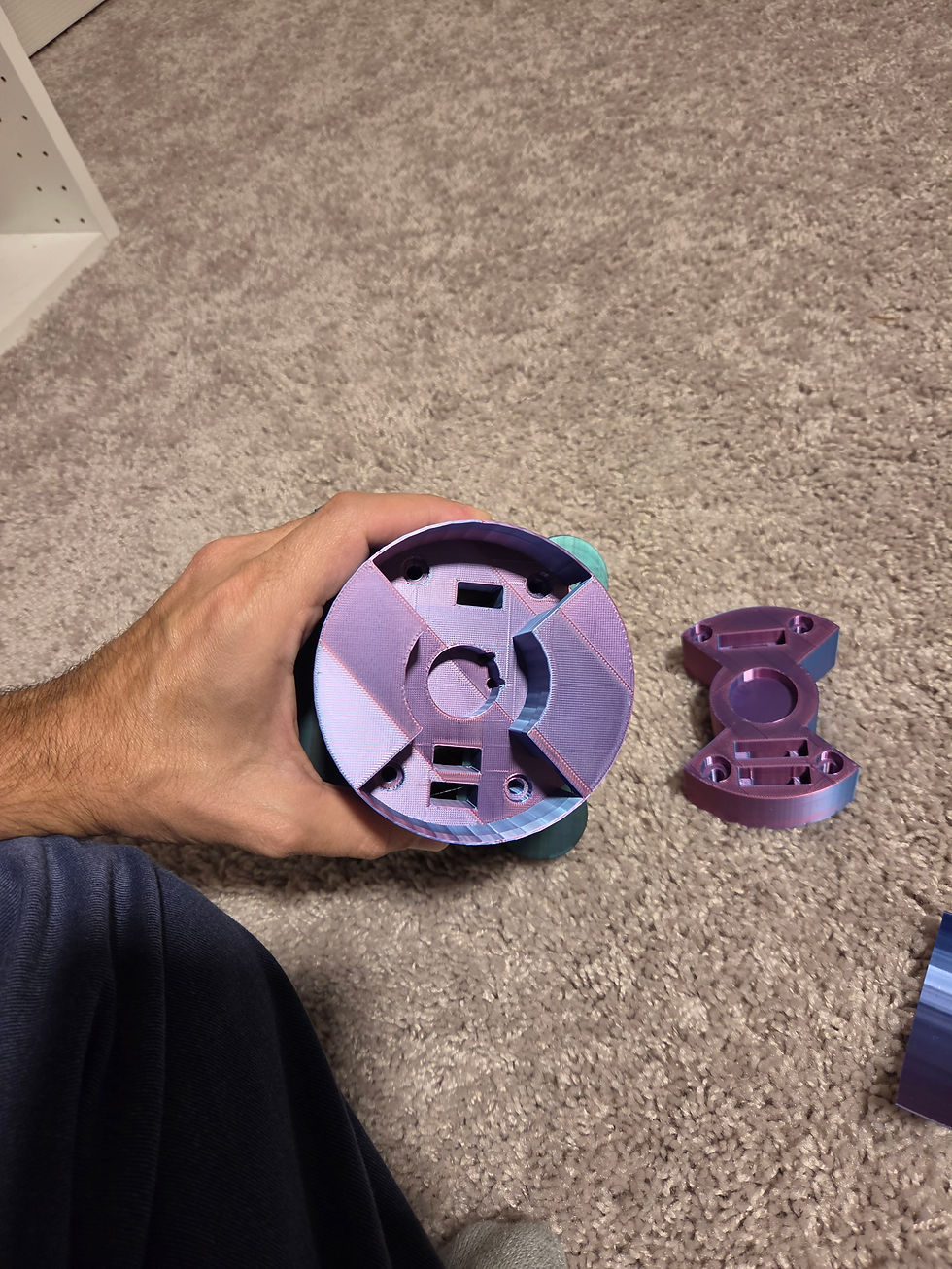
I received the new prints, and everything was slightly off with my Autocad calculations. I didn't consider that 3D-printing isn't as exact as it should be. For example, the main hole for the electromagnet is 25mm, the exact diameter of the electromagnet. But it still needed space to fit inside the hole, so I needed to increase it a bit to allow it to sink in. Since I built it modular the reprints only need a couple of hours to redo. I will receive the updated prints on Monday morning 10/11 and if all goes well should be able to assemble everything. I went out to home depot and Lowes to try to buy material for the base and couldn't because of lack of supplies they have. Tonight I plan on just ordering from Grainger or another source that is local and easy to buy form. In the meanwhile, they had enough supplies to make the platform for the base to site on.


Update: I got the new pieces from my contact and there is still major flaws even though it’s a step in the right direction. The side walls are too flimsy and break when printing. I plan on just making a quick outside support to enforce the walls. It won’t look pretty but it will be practical. The knubs on the electromagnet still interfere with the holes I designed. The manufacturer print only has the circle magnet and not the knubs. I'm going to redesign the piece to just be a solid opening to avoid anymore design flaws. The side where the locking pins are places has issues as well. The leg pieces of the locking pins are just slightly off from the holes I made. When designing this I tried to use 3D models provided by the manufacturer. Those models seem to be incorrect. Lastly I shrunk down the top interface part so it would fit, as it currently is slightly too large to go into the bottom housing. Once I finish the small tweaks, I should have things on Thursday.



Troy:
Final PCB has been sent to JLCPCB for manufacturing. Design has already cleared their manufacturing design review and been sent into production. This manufacturer includes a stainless steel stencil for rapid solder paste application. Components have also been ordered. I was able to source a reflow oven for quick assembly once everything arrives. All orders have been placed with expedited processing. In the meantime, until everything is delivered, I will begin programming of the human machine interface and the motor driver code. Below are pictures of the final PCB sent into production followed by the schematic. The PCB has 6 layers. The first picture is of just signal layers and the second picture includes the ground and power plane layers. Stackup I settled on from top down was signal, signal ground, signal, power, power ground, signal. Top signal and middle signal layers were primarily dedicated to digital and analog signals. The bottom signal layer was primarily dedicated to power components and some crossover with analog signals associated with current and voltage sensing, when switching to other layers could not be achieved due to space constraints. CANbus will interface with the PCB via an M12-5 A coded connector and STO signal will interface with the PCB via an M8-3 A coded connector. Power will pass through the PCB via Phoenix Contact Combicon connector. Electromagnets, motor phases, and hall sensors connections will follow suite with the Combicon connectors.


